This chapter is based on UG's free-form surface modeling function for 3D solid modeling of rotors. Firstly, the original data file of the blade is processed to establish the spline curve of the blade profile, and the spatial profile of the blade is constructed to more accurately reflect the curved shape of the blade, which is beneficial to the actual processing of the blade.
3 Overall processing of the impeller
The impeller machining should be completed with a 5-axis NC plus center. The 5 coordinates refer to the addition of 2 rotation axes (A, B or A, C or B, C) based on the 3 translational axes and 5 axes can be linked. . Thanks to the 2 axes of rotation, the 5-axis machine has a wide range of motion axis configurations. When the modeling is completed, the machining module in the UG software can automatically generate the CNC plus T command that the CNC machine can accept. The traditional method of impeller machining is to use different blanks for the blade and the contour, and the T is formed by welding the blade to the contour. This method is not only time consuming and laborious, but also various performances of the impeller are difficult to guarantee.
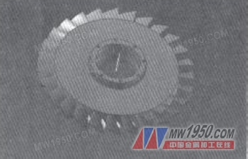
The UG system comes with three types of five-axis machine tools. In this paper, the rotary/swing type machine tool is used for virtual simulation processing. The swing axis of the oscillating head is the B axis, and the rotary axis of the turret is the C axis. The machine tool components and tool components are transferred into the machine navigator, and the impeller parts are placed on the turntable for machining simulation. The impeller uses a 5-axis CNC machine tool plus T. Because the blade is very twisted, the flow path is relatively narrow, and the tool should be reasonably oscillated on the blade and in the flow path to prevent the impeller from being overcut and to obtain a smooth blade. It can be seen from the three-dimensional model of the impeller of Fig. 6 that when the surface of the Jiading blade is heavy, the tool axis must swing between two adjacent blades and cannot collide with the blade, that is, the blade is the boundary of the flow path processing. condition. In UG, a tool axis iterative method, Interpolated M Axis, is proposed, which can control the tool axis by defining the vector direction at a specified point to produce a complete high quality impeller.
According to the blade profile characteristics, according to the way the tool is in contact with the curved surface, the five-axis CNC milling blade profile can be divided into two types: "line contact" (side edge milling) and "point contact". However, for side-edge milling, the entire side of the tool is in contact with the blade, which has a great influence on the springback of the thin blade. Therefore, side milling of such blades is only an approximate processing method. For point contact, this method has some unavoidable disadvantages: for blades with a higher degree of bending, because the space distance of the blades is relatively close, the interference between the adjacent blades during processing is difficult to avoid; "Line processing" produces a small rebound when processing thin blades, so when adding T-edge fillets, the "point processing" method is adopted. Therefore, in the overall processing of the impeller, the processing method is to combine "point processing" with "line processing".
4 Conclusion
The practice shows that the CAD/CAM technology is applied to the five-dimensional NC machine tool, and the three-dimensional solid modeling of the rotor is carried out for the structural characteristics of the impeller parts, which is more conducive to the visual observation of the designed workpiece, which greatly reduces the actual production and processing. Waste, reducing design cycles and reducing production costs.
Previous page
The utility model discloses a Kitchen Shower head that is convenient to switch the water outlet mode, has a compact structure, and is easy to use, and a kitchen faucet using the kitchen shower head. , The shower head is provided with a water separator, and the water separator is provided with an annular flow channel and an inner flow channel respectively connected to the spray water outlet body and the V-shaped water outlet body, and the lower end of the outer wall of the water separator is upwardly circular A plurality of water inlet holes connected to the annular flow channel are provided, and a first sealing ring is provided on the lower side of the water inlet hole; the water outlet end of the shower body is connected with a converter, and the converter is provided with a communicating In the water diversion cavity at the water outlet end of the shower body, the lower end of the water diversion device is installed in the water diversion cavity and can move up and down, and the upper end of the inner wall of the water diversion cavity is provided with a convex ring matching the first sealing ring, so The bottom surface of the water diversion cavity is provided with a sealing gasket that can seal the inner flow channel.
Waterfall Shower Head,Overhead Shower Head,Push Button Hand Shower,Brushed Nickel Sink Faucet
Yuyao Zelin Sanitary Ware Co., Ltd , https://www.zelinshower.com