In the teaching of mechanical equipment assembly and maintenance practice, the straightness of the guide rail is an important measurement item. Our common measuring instrument is a level meter. It is easy to use for the frame level, but the measurement reading range is very narrow. For the less accurate guide rail, the measurement cannot be taken. Therefore, the frame level is mostly used for machine level correction. Although the measuring level has a large measuring range, it is not convenient for the machine level to be corrected, and the cost is relatively high. In view of the above problems, we continuously analyze and research the measuring instruments in the teaching process. Now we have successfully studied the straightness combined measuring instruments. The specific structure and application are as follows.
1. Combination measuring instrument structure
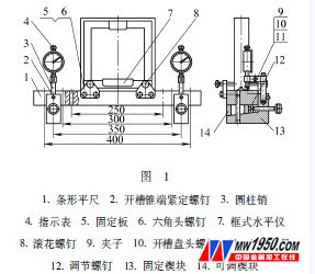
The structure of the combined measuring instrument is shown in Figure 1.
2. Combination measuring instrument usage
(1) The measuring instrument firstly positions and couples the fixed wedge 13, the adjustable wedge 14 and the strip flat rule 1 with a cylindrical pin according to the length of the guide rail, and places the frame level 7 on the strip flat 1 to ensure its The bottom surface is evenly contacted with the upper surface of the strip-shaped flat ruler 1 and fixed by screws 8. The two indicating tables 4 are fixed on the fixed wedge 13 by the clip 9 and the cylindrical pin 3. At this time, the center distance of the two indicating tables 4 is adapted to the length of the segment. (The segment length can be 400mm, 350mm, 300mm and 250mm).
(2) Place the combination measuring instrument on the flat plate, and the upper surface of the strip-shaped flat rule 1 is kept parallel with the lower surface of the fixed wedge 13 by the adjusting screw 12, and the indicator is adjusted to have an initial reading of about 0.3 mm. Then adjust to zero.
(3) The combined measuring instrument is directly placed on the machine guide rail, and the lower surface of the fixed wedge 13 is in contact with the surface of the guide rail. According to the principle of the front foot pressing the back foot during measurement, the measurement is performed on each segment one by one. Note that the position of the left-end adjustable wedge 14 does not move at each measurement, that is, the reading of the left end indicating table 4 is always zero, and the adjustable wedge 14 is moved by adjusting the right-end adjusting screw 12, and the strip-shaped flat rule 1 is driven up and down. Move, and finally center the bubble of the frame level 1 at this time, the difference between the readings at both ends of the indicator table 4 is the straightness error value of each segment (each segment reading distinguishes between positive and negative values).
(4) The straightness error value of the guide rail is determined. for example,
Set the length of the guide rail to 1500mm, and measure it in 6 sections with a combination measuring instrument (using the indicator). The measured readings are +0.15mm, +0.10mm, +0.20mm, 0mm, -0.13mm, -0.20mm. The method for solving the straightness error value of the guide rail is as follows.
Method 1: Use the graphical analysis method to find the linearity error of the guide rail. The error value is plotted according to the reading value. as shown in picture 2.
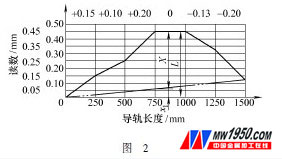
The error value is evaluated by the point-and-point method at both ends. Make a line connection at both ends, so the straightness error X can be directly obtained.
X=Lx 1 =0.45-0.12×3/6=0.39(mm)
Method 2: Calculate the straightness error of the guide rail by using the calculation analysis method. Record the readings of each segment as: +0.15mm, +0.10mm, +0.20mm, 0mm, -0.13mm, -0.20mm.
Calculate the average of the algebraic sums of the segments:
N=(+0.15+0.10+0.20+0-0.13-0.20)/6=0.02(mm)
Each reading is deducted by 0.02, which is
+0.13, +0.08, +0.18, -0.02, -0.15, -0.22
Accumulate, the coordinates of the endpoints of each segment:
+0.13, +0.08, +0.18, -0.02, -0.15, -0.22
↗↘ ↗↘ ↗↘ ↗↘ ↗↘ ↗↘
0 +0.13 +0.21 +0.39 +0.37 +0.22 0
Straightness error X can be obtained directly:
X=Xmax-Xmin=+0.39-0=0.39(mm)
3. Conclusion
The combined measuring instrument is a major breakthrough in the accuracy measurement of mechanical equipment, which greatly exceeds the measuring range of the frame level meter; the indicator table can greatly improve the measurement accuracy, and can directly read the error value of each segment from the indicator table. Can be reasonably segmented and measured on different lengths of guide rails. It has been widely used in the maintenance of machine tools in college teaching and school-enterprise units.
The auger bit adds a long deep spiral flute for effective chip removal.
Two styles of auger bit are commonly used in hand braces: the Jennings or Jennings-pattern bit has a self-feeding screw tip, two spurs and two radial cutting edges. This bit has a double flute starting from the cutting edges, and extending several inches up the shank of the bit, for waste removal.
The Irwin or solid-center auger bit is similar, the only difference being that one of the cutting edges has only a "vestigal flute" supporting it, which extends only about 1â„2 in (13 mm) up the shank before ending.
The diameter of auger bits for hand braces is commonly expressed by a single number, indicating the size in 16ths of an inch. For example, #4 is 4/16 or 1/4 in (6 mm), #6 is 6/16 or 3/8 in (9 mm), #9 is 9/16 in (14 mm), and #16 is 16/16 or 1 in (25 mm). Sets commonly consist of #4-16 or #4-10 bits.


Extra Long Auger Bit,Auger Drill Bit,Drill Bit With Flute,Carbon Steel Wood Working
Behappy Crafts (suzhou)Co.,Ltd , https://www.jshaoyue.com