3 welding tooling design
As mentioned earlier, the design of the welding tooling is quite important. There are many ultrasonic equipment suppliers in China that produce their own welding tools, but a considerable part of them are imitations, and then they are constantly trimming and testing. Through this repeated adjustment method, the coordination of tooling and equipment frequency is achieved. In this paper, the finite element method can be used to determine the frequency when designing the tooling, and the tooling test result and the design frequency error are only 1%. At the same time, this paper introduces the concept of DFSS (Design For Six Sigma) to optimize and robust design of tooling. The concept of 6-Sigma design is to fully collect the customer's voice in the design process for targeted design; and pre-consideration of possible deviations in the production process to ensure that the quality of the final product is distributed within a reasonable level. The design process is shown in Figure 2. Starting from the development of the design indicators, the structure and dimensions of the tooling are initially designed according to the existing experience. A parametric model is established in ANSYS, and then the model is determined by the simulation experiment design (DOE) method. Important parameters, based on robust requirements, determine the value, and then use the sub-problem method to optimize other parameters. Taking into account the influence of materials and environmental parameters during the manufacture and use of the tooling, it also designed tolerances to meet the manufacturing cost requirements. Finally, the manufacturing, test and test theory design and actual error, to meet the design indicators that are delivered. The following step-by-step detailed introduction.

Figure 2 design flow chart
3.1 Geometry design (establishing a parametric model)
The design of the welding tool is first to determine its approximate geometric shape and structure, and to establish a parametric model for subsequent analysis. Figure 3a) is the design of the most common welding tooling, in which a number of U-shaped grooves are opened in the direction of vibration on a material of approximately cuboid. The overall dimensions are the lengths of the X, Y, and Z directions, and the lateral dimensions X and Y are generally comparable to the size of the workpiece being welded. The length of Z is equal to the half wavelength of the ultrasonic wave, because in the classical vibration theory, the first-order axial frequency of the elongated object is determined by its length, and the half-wave length is exactly matched with the acoustic wave frequency. This design has been extended. Use, is beneficial to the spread of sound waves. The purpose of the U-shaped groove is to reduce the loss of lateral vibration of the tooling. The position, size and number are determined according to the overall size of the tooling. It can be seen that in this design, there are fewer parameters that can be freely regulated, so we have made improvements on this basis. Figure 3b) is a newly designed tooling that has one more size parameter than the traditional design: the outer arc radius R. In addition, the groove is engraved on the working surface of the tooling to cooperate with the surface of the plastic workpiece, which is beneficial to transmit vibration energy and protect the workpiece from damage. This model is routinely parametrically modeled in ANSYS, and then the next experimental design.
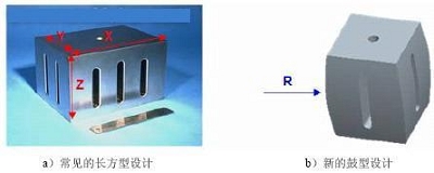
Figure 3 tooling exterior design
3.2 DOE experimental design (determination of important parameters)
DFSS is created to solve practical engineering problems. It does not pursue perfection, but is effective and robust. It embodies the idea of ​​6-Sigma, grasps the main contradiction, and abandons "99.97%", while requiring the design to be quite resistant to environmental variability. Therefore, before the target parameter optimization, screening should be carried out to pick out the size that has an important influence on the structure, and determine their values ​​according to the robustness principle.
3.2.1 DOE parameter setting and DOE
The design parameters are the size of the tooling and the size of the U-shaped groove, etc., a total of eight. The target parameter is the first-order axial vibration frequency because it has the greatest influence on the weld, and the maximum concentrated stress and the difference in the working surface amplitude are limited as state variables. Based on experience, it is assumed that the effect of the parameters on the results is linear, so each factor is only set to two levels, high and low. The list of parameters and corresponding names is as follows:
Table 1 Comparison design parameter comparison table

DOE is performed in ANSYS using the previously established parametric model. Due to software limitations, full-factor DOE can only use up to 7 parameters, while the model has 8 parameters, and ANSYS's analysis of DOE results is not as comprehensive as professional 6-sigma software, and can't handle interaction. Therefore, we use APDL to write a DOE loop to calculate and extract the results of the program, and then put the data into Minitab for analysis.
3.2.2 Analysis of DOE results
Minitab's DOE analysis is shown in Figure 4 and includes the main influencing factors analysis and interaction analysis. The main influencing factor analysis is used to determine which design variable changes have a greater impact on the target variable, thereby indicating which are important design variables. The interaction between the factors is then analyzed to determine the level of the factors and to reduce the degree of coupling between the design variables. Compare the degree of change of other factors when a design factor is high or low. According to the independent axiom, the optimal design is not coupled to each other, so choose the level that is less variable.

Figure 4 DOE results analysis
The analysis results of the welding tooling in this paper are: the important design parameters are the outer arc radius and the slot width of the tooling. The level of both parameters is "high", that is, the radius takes a larger value in the DOE, and the groove width also takes a larger value. The important parameters and their values ​​were determined, and then several other parameters were used to optimize the design in ANSYS to adjust the tooling frequency to match the operating frequency of the welding machine. The optimization process is as follows.
Previous Next
A luxury Ceiling Lamp is a high-end lighting fixture that is designed to add elegance and sophistication to a room. These lamps are often made with high-quality materials such as crystal, brass, or gold, and feature intricate designs and details. Luxury ceiling lamps are typically larger in size and provide a focal point in a room, whether it be in a grand foyer, dining room, or living space. They often incorporate multiple light sources and can be dimmable, allowing for customizable lighting options. Some luxury ceiling lamps also come with additional features such as remote controls, adjustable heights, or integrated smart technology for ease of use. Overall, a luxury ceiling lamp is a statement piece that not only provides functional lighting but also enhances the overall aesthetic and ambiance of a space.
Luxury Ceiling Lamp,Crystal Ceiling Lamp,Glass Ceiling Lamp,Luxury Ceiling Light
Zhongshan Seekyo Lighting CO., Ltd. , https://www.seekyolighting.com