The excavator is a road repair work equipment, equipped with a variety of work devices, through the replacement of different work devices, can achieve a multi-functional machine. The excavator consists of a lower part (tracked chassis), an upper turret, main components and various working devices.
For the virtual prototyping simulation software ADAMS, although it is known for its simulation analysis of mechanical systems, its 3D geometric modeling function is weak. It takes a lot of time to complete the modeling work for complex 3D models, and it can not guarantee the model. Dimensional accuracy. In this paper, the powerful SolidWorks entity design software is used to complete the 3D solid modeling of the main components of the excavator. The prototype geometry model is transformed and imported into the ADAMS/View environment to generate a virtual prototype and complete the simulation analysis.
1 SolidWorks-based part modeling and machine assembly
3D solid modeling is the mainstream method of current product design. Among many 3D CAD software, SolidWorks is unique and has become the software of choice for many designers. The excavator belongs to a complex mechanical structure. Considering the number of constraints that SolidWorks has to import into ADAMS, especially the time and success rate of ADAMS for simulation analysis of main components, it is omitted in SolidWorks. Construction of some component geometry models that do not require analysis. The functions of these components can be implemented by adding constraints, friction, etc. to the ADAMS. This reduces the number of parts in the ADAMS and reduces the total number of constrained pairs between the parts, which reduces the time required for ADAMS simulation and ensures the success rate of the simulation test.
According to whether there is relative motion (regardless of the walking movement and the working condition when the car is replaced with other working devices), the working parts of the excavator are divided into: boom, stick, bucket, bucket rocker, bucket link There are 11 large moving parts in the boom hydraulic cylinder, boom hydraulic cylinder piston rod, stick hydraulic cylinder, stick hydraulic cylinder piston rod, bucket hydraulic cylinder and bucket hydraulic cylinder piston rod.
The models of each part are separately established in SolidWorks, and finally assembled, and the assembly model of the main components of the vehicle is shown in Fig. 1.
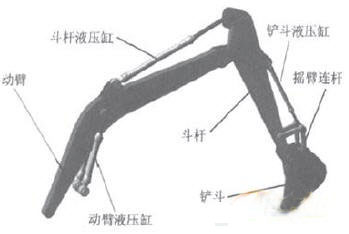
Figure 1 3D assembly model of the main components
2 Simulation analysis based on ADAMS
2.1 Establishment of virtual prototype
There are two ways to simulate ADAMS. The first way is to know the dynamic parameters such as force and load, and to change the kinematic parameters such as speed, acceleration and displacement of the system; the second way is to know the motion trajectory and acceleration of the system. The kinematic parameters such as displacement, and the changes in the dynamic parameters such as the force and load of the system. In this paper, the main part of the excavator is simulated in the second way, that is, a part of the excavation trajectory is obtained by the movement of the boom hydraulic cylinder, the arm hydraulic cylinder and the bucket hydraulic cylinder, and the hydraulic cylinders are calculated in the simulation. The displacement motion function is used to obtain the kinematics and dynamics curves of each moving member.
To import a 3D solid model created in SolidWorks into an ADAMS environment, both software must have the same geometry data transformation module. For SolidWorks software, the Parasolid format is preferred. The specific operation is to save as Parasolid format in SolidWorks; select import a file in the welcome interface of ADAMSNiew, then select Parasolid format in file type and specify the location of Parasolid format file.
After importing a SolidWorks model into ADAMSNiew, you need to manually add the mass properties for each part. In addition, the original assembly relationship in the model has been invalid, but the initial position of each component is provided. In fact, the components exist independently in the ADAMS without any relationship, and are not virtual prototypes with realistic meaning. The work to be done at this time is to "assemble" the components into a whole in ADAMSNiew. The virtual prototype is shown in Figure 2. The coordinate system used below is based on the coordinate system given in the figure.
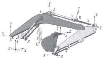
Figure 2 Virtual prototype diagram of the main components
2.1.1 Adding Constraints
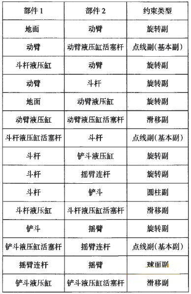
When it is as close as possible to the real situation, add constraints between the components, as shown in Table 1.
2.1.2 Adding a driver
Table 1 Constraint allocation of simulation models
During the excavation process of the main components, while the boom cylinder is fully contracted, the arm cylinder and the bucket cylinder are also contracted accordingly, and then the arm cylinder extends to the maximum length to realize excavation, while the boom cylinder extends The bucket is raised and the bucket cylinder is extended to keep the upper end of the bucket horizontal. According to the actual movement process of each hydraulic cylinder, motion is added to each of the hydraulic cylinder slip pairs, and the movement mode is displacement, and the displacement functions of the boom cylinder, the arm cylinder and the bucket cylinder are respectively input.
The displacement function curves of the respective cylinders are shown in Figs. 3 to 5 .

2.1.3 Checking the model
After the prototype model is built, the model is verified and the correct information is displayed. The accuracy of the model is guaranteed and the simulation of the prototype is prepared.
2.2 Simulation analysis of main components
2.2.1 Definition test
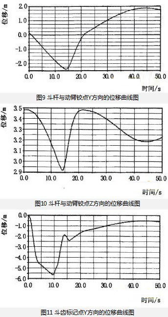
Direct tests can be built on the data of the model elements via the menu Build→Measure→Select Object→New. Create a Marker point at the tip of the bucket tooth and create two measurements (Measure), define the measurement feature as a Translational displacement, and measure the displacement component of the marker along the Y and Z directions (dy and Dz).
2.2.2 Simulation calculation
When performing simulation calculations in ADAMS, you only need to specify the simulation type, simulation time, step size or number of steps in the simulation calculation. ADAMS/View automatically calls the ADAMS/Solver solver to complete the simulation analysis. After the simulation analysis is completed, the program automatically returns to the ADAMS/View interface. In this paper, the simulation time is set to 50s and the number of simulation steps is 100.
2.2.3 Post-processing of results
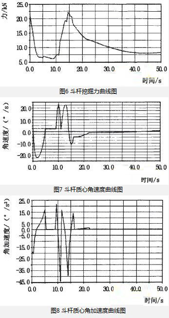
The simulation results are imported into the ADAMS/Postprocess module for post-processing of the results. The ADAMS/Postprocess module outputs the kinematics and dynamics characteristic curves of each moving member (such as the angular velocity of the boom, the arm and the bucket centroid, the angular acceleration, the absolute angular velocity of the stick and the boom, the bucket and the stick, Angular acceleration; change in positional coordinates of the hinge point; lift of the boom, digging force of the stick and bucket, etc.) and established characteristic curve of the physical quantity of the test.
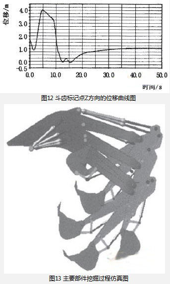
In this paper, the stick is taken as an example, and the digging force, the centroid angular velocity, the centroid angular acceleration and the displacement of the boom hinge point along the Y and Z directions are output, as shown in Fig. 6 to Fig. 10, Fig. 11 and Fig. 12 shows the displacement curve of the tooth mark point in the Y and Z directions (the coordinate system is the coordinate system shown in Fig. 2), and Fig. 13 shows the entire simulation process of the main device. From the obtained kinematic characteristic curve, the rationality of the mechanism design can be verified, and a reference can be provided for optimizing the geometrical dimensions of each component; the dynamic curve can verify whether the design meets the requirements before producing the physical prototype, or under the limit working condition. Provide a basis for strength checking and improved design of related components and intelligent control of the organization.
3 Conclusion
(1) Applying the 3D CAD software SolidWorks to establish the model of each part of the main components of the digging machine, and complete the assembly of the whole machine; and directly in the ADAMS review modeling Fuyuan, reducing a large amount of modeling time and virtual The prototype generation and simulation analysis laid the foundation.
(2) The conversion and import of the model from SolidWorks to ADAMS/View is completed, and the constraints and drives are added reasonably, and the virtual prototype of the main components is generated; the simulation calculation and the post-processing of the results are performed in ADAMS, and the results are analyzed. The rationality of the design can be verified and the basis for subsequent finite element analysis and optimization design.
(3) Applying mature 3D CAD software modeling, relying on powerful multi-body dynamics analysis software for simulation analysis, giving full play to the advantages of each software, reducing workload, shortening working time, and ensuring simulation analysis Credibility is an efficient design method that integrates CAD/CAE integration technology into mechanical design, and has certain reference value for the development and design of other products.
Ultra Plantâ„¢ Grow Light offers One Chip Technology aimed to meet your indoor growing expectation such as improve plants' quality, increase yield, or better the margin, etc., all for helping you realize a higher return on your crops.
Ultra Plantâ„¢ Grow Light is combined our advanced All-In-One technology with patented optical design and customized light full spectrum supported from our experienced LED engineers, plant specialists and other partners working on horticulture.
From Ultra Plantâ„¢ APP, you are able to schedule the growing process including photoperiod, brightness and spectral in advance. The lighting system will help you grow smarter, easier and better.
Ultra Plantâ„¢ is the most versatile horticultural grow lighting fixture for indoor plants with flexible full spectrum, brightness control and uniform, wider light distribution, suitable for top lighting of all types of crops. No matter it applies to anywhere for any crop, Ultra Plantâ„¢ can do perfect work for you.
Grow Light On Fruiting,Grow Light Fruiting,Fruiting Grow Lights,Bset Grow Light On Fruiting
Feton Corporation , https://www.ultraplantgrowlights.com