An effective CAE analysis must establish a finite element model quickly and efficiently. The efficiency and quality of the finite element model is largely determined by your CAD geometry. How to quickly acquire CAD geometry is not based on general finite element processing. The poor physical modeling tool that comes with the device directly acquires the geometric source directly from the CAD system. This avoids repeated modeling and ensures the consistency of design and analysis or CAD/CAE coordination. So now the CAE pre-processing software provides a data conversion interface with CAD: there is a direct interface (such as UG, Pro/E.prt, CATIA model, CATPart, etc.) that can directly read the CAD original file format. Common intermediate data formats (eg Parasolid, Acis, STEP, VDA, etc.). Is the problem of data conversion solved? Actually, many customers are complaining that they have bought a lot of CAD interfaces with a lot of money, but they have to spend a lot of time and effort to repair CAD geometry for bad models. Analysts are always complaining that the quality of CAD models produced by designers is too poor, sometimes causing wrangling between the design department and the analysis department. And in fact, the CAD conversion interface provided by the general CAE pre-processing has the following two weaknesses:
1. Data conversion is very time consuming. A complex CAD model often takes tens of minutes or even hours.
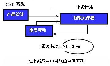
2. The converted model is of poor quality. Face loss in the model often occurs, and even the auxiliary line is dropped, resulting in repeated labor. According to statistics, analysts have 50%-70% of the time in repetitive labor.
Types and causes of CAD/CAE data conversion problems
The main causes of data conversion problems are the following five categories, and in many cases, they overlap and relate to each other.
Structurally
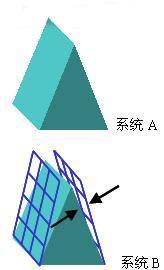
Structural problems concern whether the shape and entity of the model are correctly defined and related. For example, a model that should be a three-dimensional entity may only have a face in the target application (or even worse, only wireframes). These problems may be due to the use of Different modelers (wireframes, surfaces, solids, or blends), or because they are not fully understood during output from the source system.
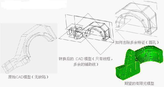
The following figure is a simple example of a typical structural synergy problem. The model is a solid part in the original CAD system, and there is no entity definition in the output to the downstream FEA application and only the auxiliary line is left in the file. The usual CAD interface can only press one button (at most only a few options)
At this point, the analyst can only identify and extract the solid model by himself. Perhaps it is easy to regenerate the part model for analysis from the sketch. It may be easy to rebuild the part, but he can accept it from the perspective of user quality assurance (QA). ? More importantly, it is impractical for a large complex part like an engine body. In this example, data exchange is no problem, all data is output to the file, and no data exchange error message is reported. , but the data is not available to the recipient.
2. Precision
This may be the main cause of many data conversion problems because different geometric modeling cores either have a fixed tolerance range or provide a variable tolerance capability that allows the user to determine the required accuracy based on his or her own work.
Some systems use absolute tolerances, such as 0.005mm or 0.01mm, while others use tolerances relative to model dimensions, such as 10-4 times the model size; others have different tolerances for different unit systems. Others do not consider the unit at all!
The effect is that models that are well represented in a looser modeling system are broken in a receiving system due to too large tolerances. These entities appear to be disconnected or even beyond the required capacity. The difference, and the serious design intent problem, there is a short side or a small side in a system, but it is swallowed up by a large tolerance in a downstream receiving system. .
Next page
Turbine Flowmeter,Turbine Flow Meters,Electromagnetism Flow Meter,Turbine Wheel Flow Meter
Jingsu Huaerwei Science and Technology Group Co.,Ltd , https://www.hewflowmeter.com