Fives. Making DAC curves
Making DAC curves with CSK-3A test block
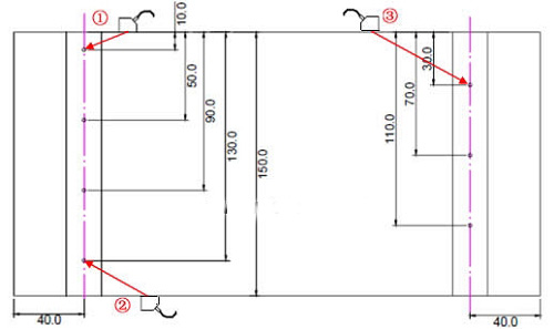
Step 1: Move the probe to find the highest echo with a hole depth of 10mm, and cover the wave with the A gate. Press the “+†key to increase the calibration point to “1â€.
Step 2: Move the probe to find the highest echo with a hole depth of 20mm, and cover the wave with the A gate. Press the “+†key to increase the calibration point to “2â€;
Two calibration points have been added and the DAC curve has been generated. According to the needs of flaw detection, you can continue to find the highest echo of the reflector with a hole depth of 30, 40, 50mm, etc., so that the calibration point is increased to 3, 4, and 5. The DAC curve is completed.
Step 3: Input criteria and compensation
On the DAC2 menu, set the penalty line offset to +5dB, the quantitation line offset to -3dB, and the evaluation line offset to -9dB.
Test block type | Plate thickness mm | Rating line | Quantitative line | Rebel line |
CSK-IIA | 6~46 | Ф2×40-18dB | Ф2×40-12dB | Ф2×40-4dB |
46~120 | Ф2×40-14dB | Ф2×40-8dB | Ф2×40+2dB | |
CSK-IIIA | 8~15 | Ф1×6-12dB | Ф1×6-6dB | Ф1×6+2dB |
15~46 | Ф1×6-9dB | Ф1×6-3dB | Ф1×6+5dB | |
46~120 | Ф1×6-6dB | Ф1×6 | Ф1×6+10dB | |
CSK-IVA | 120~400 | Фd-16dB | Фd-10dB | Фd |
six. On-site inspection
1. After power on, select the channel number, call up the dac curve, set the scale mode to depth (or level), and set the surface compensation dB number (general input compensation 2 ~ 4dB).
2. Adjust the “Workpiece Thickness†in the “Probe†function to 2 times the thickness of the plate to ensure that the screen can display the second wave scanning waveform of the probe to avoid missing detection.
3. In the case of flaw detection, the vertical welding of the probe is generally carried out and the zigzag scanning is performed along the welding mouth (that is, the movement path of the probe is serrated).
4. The distance the probe moves along the weld (front and rear): 0 ~ 100mm (eg: below)
Calculation method: starting point (position 2): 0
End point (position 2): S=2KT=2×2×25=100mm (where K is the probe slope and T is the workpiece thickness)

5. The speed at which the probe moves along the weld (left and right): ≤1.5 m/min.
Seven. Store flaw detection waveforms and data
Store the flaw detection waveform and data to the corresponding group number.
Eight. Connect the UTD600 to a computer and upload the flaw detection waveform and data to the computer to generate a flaw detection report.
Previous page
Wire Spring,Double Torsion Spring Design,Spring Steel Wire,Stainless Steel Spring Wire
OEM order and ODM order can is welcome
wire thickness : 0.07--5mm
applicaiton: viation,automotive, motorbike, bicycle, automatic equipment, household appliance, medical device ,toy, telecommunication,computer, instrument and meter,furniture, electric tools,mold and other industries
Wire Spring,Double Torsion Spring Design,Spring Steel Wire,Stainless Steel Spring Wire
Shenzhen Lanejoy Technology Co.,LTD , https://www.ccls-vaccine.com