With the continuous development of technology and industrial production, pipe manufacturing parts have been widely used in aviation, engineering machinery, agricultural machinery, petrochemical, light industry and transportation industries. Therefore, pipe processing plays an important role in contemporary industrial production. . In actual production, pipe processing varies greatly depending on the shape, size, and application.
1. Introduction of parts
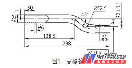
Figure 1 shows the supporting pipe parts of the automobile manufacturing industry. The material is 20 steel, the pipe diameter is D=25mm, the wall thickness is t=1mm, and the annual output is 100,000 pieces. The ellipticity does not exceed 2 mm. No defects such as scratches, pits, wrinkles, etc. are allowed on the surface of the pipe. In the trial production, the drilling, bending, and shaping processes are used, and the processing methods have the following quality problems.
(1) The conventional drilling process has low efficiency and large deformation of the drilling part.
(2) It is formed by bending on the bending machine, and only one part can be bent at a time. Because the distance between the straight sections of the two curved parts of the part is very short, the forming block can not guarantee the parallelism of 0.5mm.
(3) The rebound is large, the repairing process is laborious and time consuming, the surface quality of the parts is poor, and the scrap rate is high.
2. Process analysis
The analysis of the parts in Fig. 1: 1 The φ 6mm hole at both ends of the opening of the part is not high in precision, and the punching and punching is used to meet the requirements of use and high efficiency. 2 The distance between the straight sections of the two curved parts is very short, and the bending radius is larger than the minimum bending radius (R min=1.5D). The mold is formed once, and the shaping process is omitted. 3 The end of the part is straight and long, and the forming cavity is inclined at a certain angle when designing the mold to ensure the forming size and parallelism. 4 When designing the forming mold, the rebound factor must be fully considered so that the bending radius and the bending angle are smaller than the pattern size. In addition, the forming lower mold is slightly deeper than the forming upper mold cavity, and the ellipticity requirement of the part is required.
3. Mold structure and working process
(1) The structure of the punching die is shown in Fig. 2. With cantilever type hedging, one stroke can simultaneously punch out two opposite holes on the pipe wall. The two punches 7, 12 are respectively mounted on the fixing plate, and the female die is press-fitted on the bracket 9. The bracket is guided by the guiding column 1 and can be moved up and down. The sliding button 3 is mounted on the bracket and slides along the sliding slot of the guiding column to ensure that the bracket does not rotate relative to the guiding column.
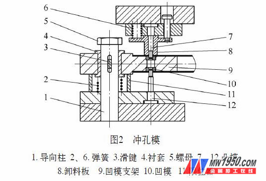
Mold working process: The workpiece is placed on the die bracket and positioned by the bracket step. Downstream of the upper die, the unloading plate contacts the die holder, the slider continues downward, the die holder slides along the guide post, and the punches 7, 12 enter the die 10, and the two holes in the pipe wall are punched out. The mold runs to the bottom dead center, and the die holder reaches the upper plane of the stopper, and the blanking ends.
The mold design should pay attention to the following problems: 1 Using the die to punch the punching holes, the punch strength must be considered in the design to prevent breakage. 2 Reasonably design the leakage hole to ensure the clean and smooth waste, so as to reduce the quality problem of punching burrs caused by excessive accumulation of waste. 3 The upper and lower springs must be designed to ensure that the mold slides flexibly.
(2) The structure of the bending die is shown in Fig. 3. Using the positioning plate 4, the nut 8, the screw 7, the length of the forming part can be flexibly adjusted to overcome the dimensional error caused by the workpiece swaying; the size of the upper and lower dies is corrected by multiple adjustments, and the forming requirements are met after the forming; the upper and lower model cavities are always with the parts Contact to ensure the ovality requirements and appearance quality of the parts.
Mold work process: The workpiece is placed on the lower mold and positioned by screws. When the slider is descending, the lower mold first comes into contact with the workpiece, the longer end is bent, the press slider is further lowered, and the workpiece is completely formed. When the slider reaches the upper plane of the mold adjustment lever, the mold is closed and the forming is completed.

Mold design points: 1 The lower mold should be 1mm higher than the semi-arc surface when designing, and the upper mold should be 1mm lower than the semi-arc surface. The arc surface of the upper and lower molds should be smooth transition, as shown in Figure 4. 2 In the case of sufficient processing methods and capabilities, the upper and lower molds are preferably constructed with inserts for easy adjustment and replacement.

4. Conclusion
After the mold is put into production, it meets the product quality and production requirements and has achieved good economic results. The punching and bending of this type of pipe has accumulated experience for similar pipe processing.
Chongqing Xingjida Import and Export Trade Co., Ltd. , https://www.xjdvalve.com