The parts shown in Figure 1 were finished on a CK7815 CNC lathe. In the figure, φ85mm is not processed, and a finishing procedure is required.
(1) Firstly, according to the requirements of the drawings, the process route is determined according to the processing principle of the first and second.
1) Cut the outer contour surface from left to right. The route is: chamfering - the actual outer circle of the cutting thread - the cutting taper part - turning φ62mm outer circle - chamfering - car φ80mm outer circle - cutting arc part - car φ80mm outer circle.
2) Cut the groove of 3mm xφ45mm.
3) The thread of the car M48x1.5.
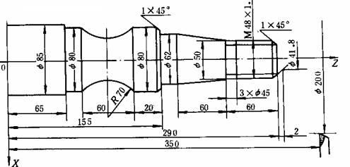
figure 1
(2) Select the tool and draw the tool layout
Three tools are required according to the processing requirements. No. 1 cutter outer circle, No. 2 knife slot, No. 3 cutter thread. When drawing the tool layout drawing, the tool change point should be correctly selected to avoid collision between the tool and the machine tool, workpiece and fixture during tool change. In this case, the tool change point is selected as A (200, 350) point.
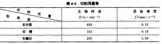
(3) Determine the amount of cutting ( as shown in Table 4-6 )
(4) Preparation of finishing procedures
The machine can be programmed with absolute value and incremental value. The absolute value is X and Z address, the incremental value is U and W address, and the decimal point is used for programming.
N0l G50 X200.2350.; (coordinate system setting)
N02 S630 M03 T0101 M08;
N03 GOO X41.8 Z292.;
N04 G01 X47.8 Z289. FO.15; (chamfering)
N05 U0 W-59.O; (φ47.8mm)
N06 X50. OW0; (retraction)
N07 X62. W-60.; (taper)
N08 UO Zl55.; (62mm)
N09 X78. W0; (retraction)
N10 X80. W-1.0; (chamfering)
Nll UO W-9.0; (car φ80mm outer circle)
N12 G02 UO W-60. I63.25 K-30.; (arc)
N13 G01 UO Z65.; (car φ80mm outer circle)
N14 X90. W0;
N15 GOO X200. Z350.M05 T0100 M09 (retraction)
N16 X51.Z230.S315 M03 T0202 M08;
N17 G01 X45.WO FO.16; (grooving)
N18 G04 X5.; (delay)
N19 GOO X51.; (retraction)
N20 X200. Z350. M05 T0200 M09; (retraction)
N21 G00 X52. Z296.S200 M03 T0303 M08;
N22 G92 X47.2 Z231.5 F1.5; (cut thread)
N23 X46.6:
N24 X46.2,
N25 X45.8;
N26 G00 X200. Z350.T0300; (return to the starting point)
N27 M30;
Check Valve,Control Check Valve,Flanged Check Valve,Threaded Valve
Zhejiang Philic Fluid Control Co.,LTD , https://www.philicflow.com